-
29th December 2012, 05:45 PM
#1
 RLI's step by step wiring and gauges install!
G'day Trendsetters,
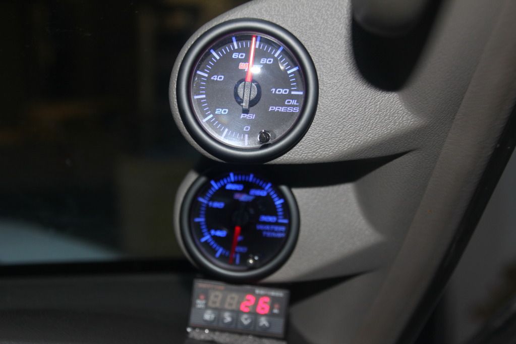
The following is how i wired up my auto-meter, glow-shift and sine-tec gauges!
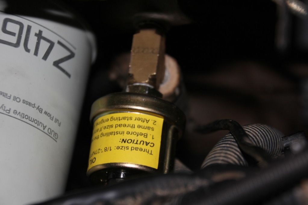
Oil pressure sender!
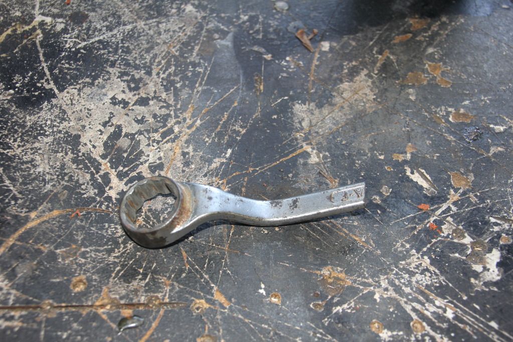
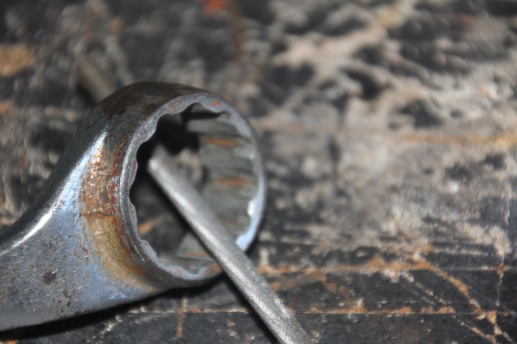
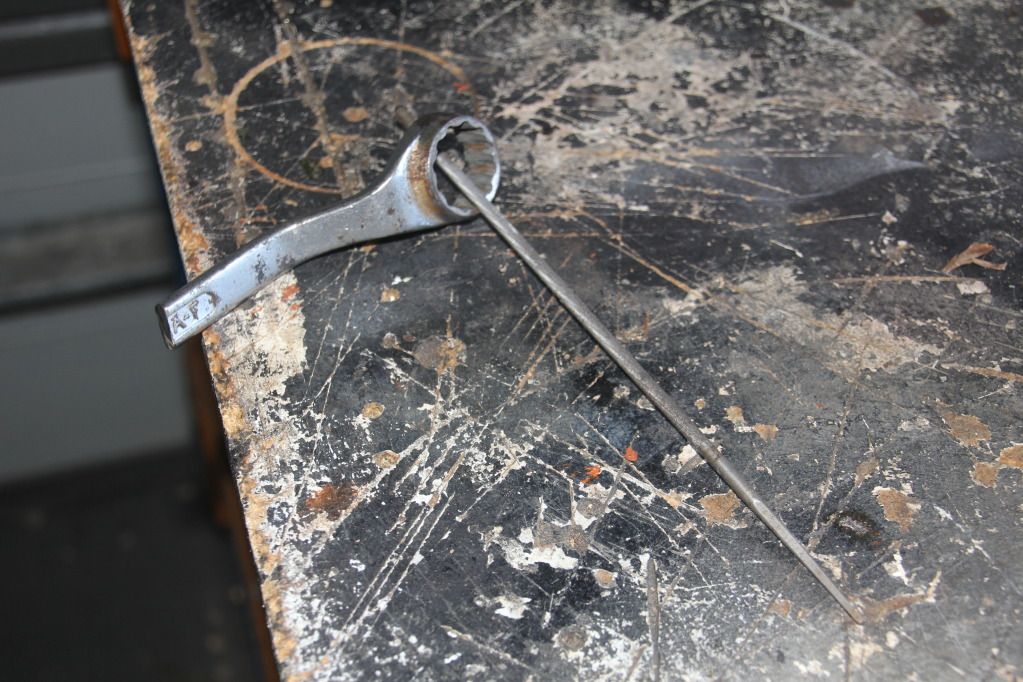
First remove the original oil pressure sender unit which is located next to the oil filter closest to the radiator. So you don not have buy a genuine $50.00 Nissan socket. I modified and cut down an old 1 inch AF ring spanner. I cut the length to 125mm. Using a round file, file back all the inside teeth so they are all rounded. A cheap supercheap spanner would probably cost you about $2.00 and fifteen minutes filing.
I then purchased a brass block fitting from my local Pirtek store. (when purchasing the block, take both the Nissan and after market oil pressure sender units to the store, so they can match the threads accordingly) Now that i have my brass fitting, firstly, i fit the Nissan oil pressure sender unit to the top of the brass block (don't forget to use thread ntape)
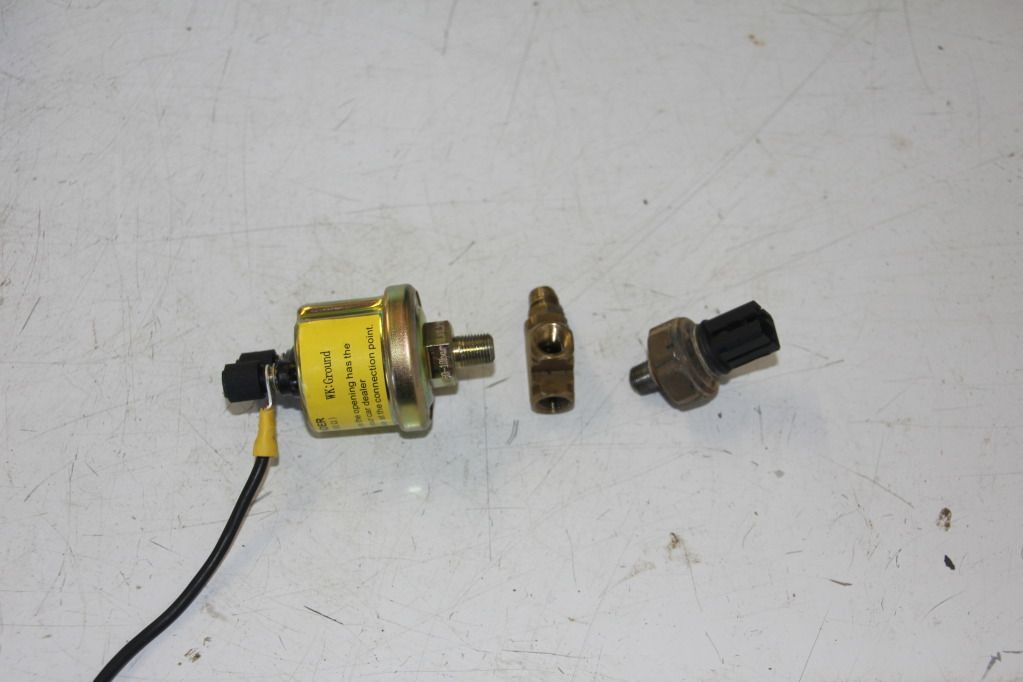
Secondly, Now fit the brass block fitting with the Nissan oil pressure sender unit to the engine block using a 6inch shifter (don't oven tighten) Then fit the aftermarket sender unit at the end of the brass block fitting facing towards the drivers side guard.
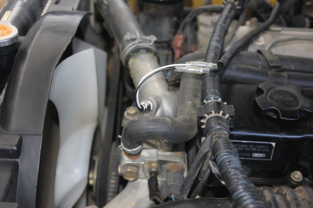
Remove factory plug from thermostat housing and Fit water temp sensor fitting here. Remember to use thread tape! If your fitting will not fit, go to your local Pirtec store with thermostat housing and your sensor, so you can fit a reducer two way fitting.
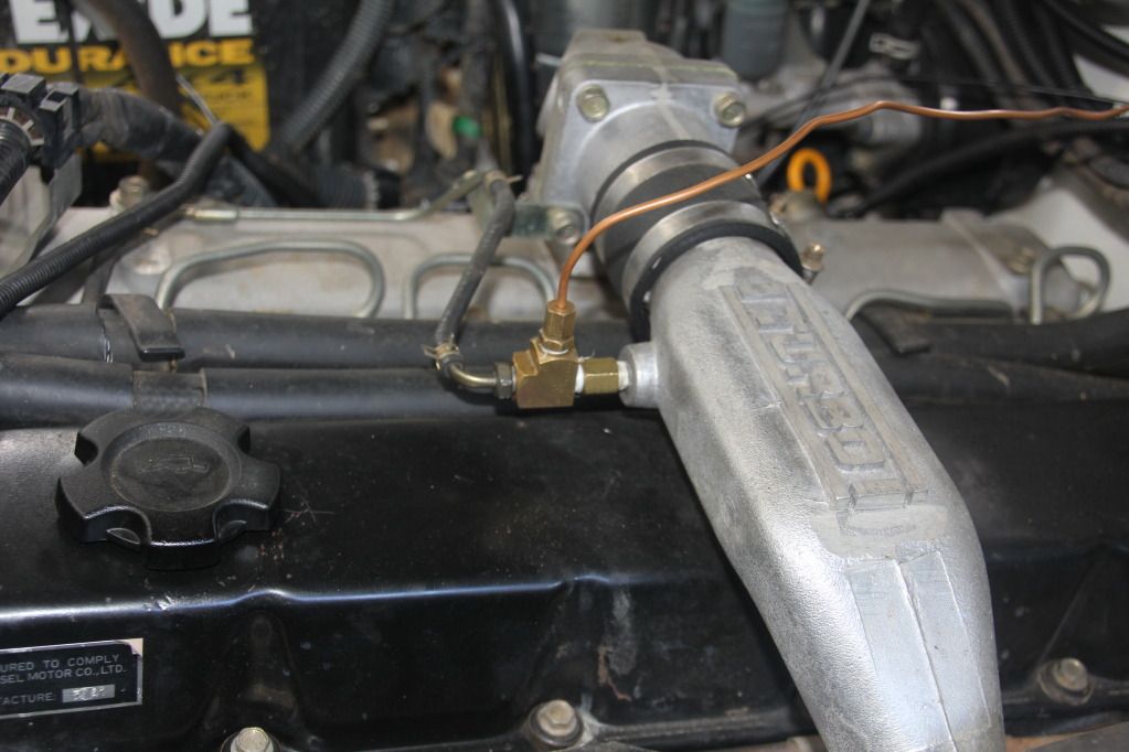
Boost fitting!
Run copper line through fire/wall into dash area. Tap into boost line on manifold from inlet side of turbo.
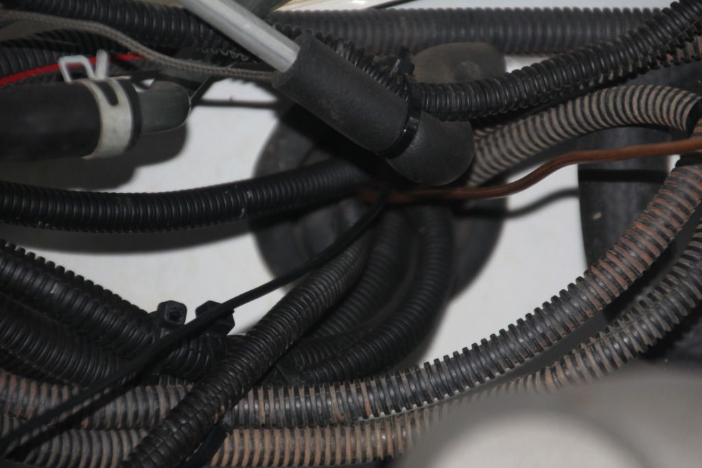
Run all wiring and lines ie, Boost, Dual battery monitor, EGT, Oil pressure and Water temp through this spot in the fire/wall. I like to use flexible conduit to help protect my wiring.
More to follow over!
Last edited by PMC; 2nd January 2013 at 02:50 PM.
The halls been rented the bands been paid, time to see you dance!

-
The Following 3 Users Say Thank You to PMC For This Useful Post:
MC97GQ (29th December 2012), NissanGQ4.2 (1st January 2013), patolman72 (20th December 2015)
-
29th December 2012 05:45 PM
# ADS
Circuit advertisement

-
29th December 2012, 05:51 PM
#2
Part 2
Wiring:
Black wire goes from neg terminal on the back of the aftermarket oil sender unit to the negative terminal on the battery. White wire goes from remaining terminal on the back of the aftermarket sender unit back through drivers side firewall up into pillar pod into terminal clip to gauge.
Water temp the same. Run EGT wiring from dump pipe through fire-wall as with previous wires. Same goes for Boost line.
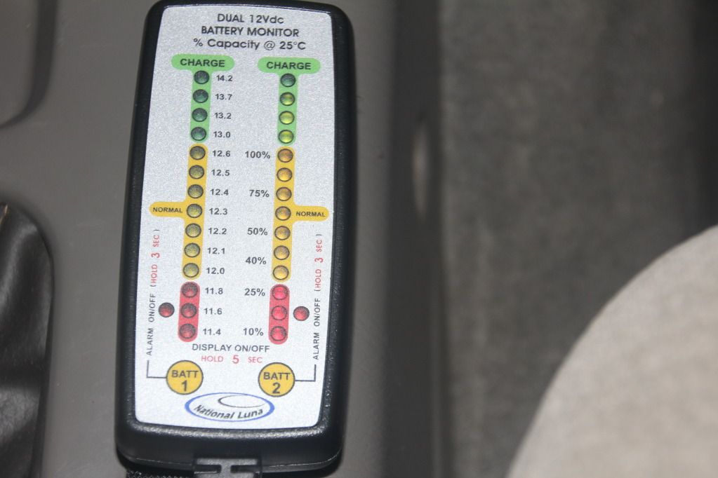
Dual battery monitor wiring. Battery 1, fit black wire to neg on battery terminal. Fit red wire to positive on battery terminal. Remember to fit a 3 amp inline fuse to both positive red wires to the battery terminals. Battery 2 the same as for Battery 1. Note: You will have to solder extra lengths of additional wiring to the dual battery monitor loom.
INSIDE THE CABIN:
Firstly, we need to get access to our areas of operations ie; pillar Pod, under the dash and the cigarette lighter area.
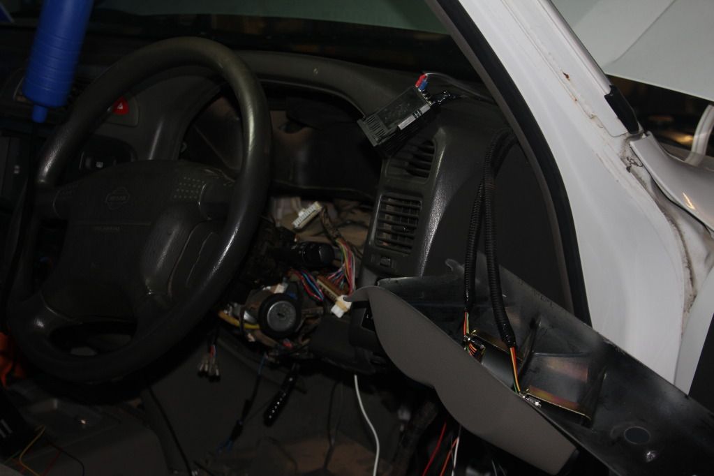
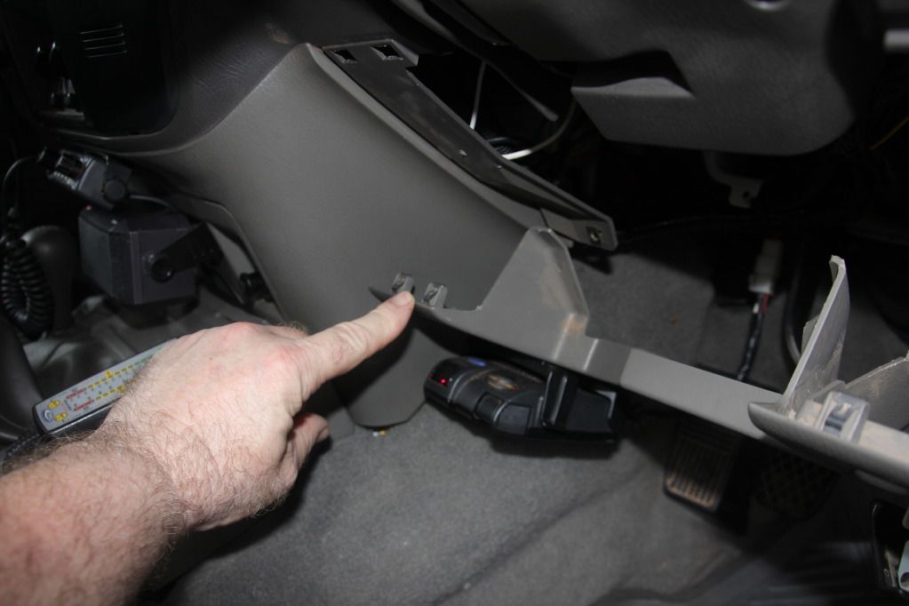
To access the pillar Pod area, using a Phillips head screw driver remove the grab handle on the drivers side! Now Grab the pillar trim at the top and gentle pull back towards you, with the blade of the screw driver now lever the trim free from the mounting clips. Now look at the following photo, using a 10mm small socket or large Phillips head screw driver we need to remove the both the bonnet and fuel cap release latches.
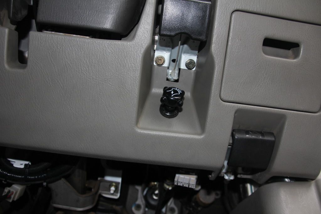
Now remove the following screw, see photo.
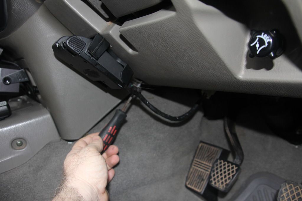
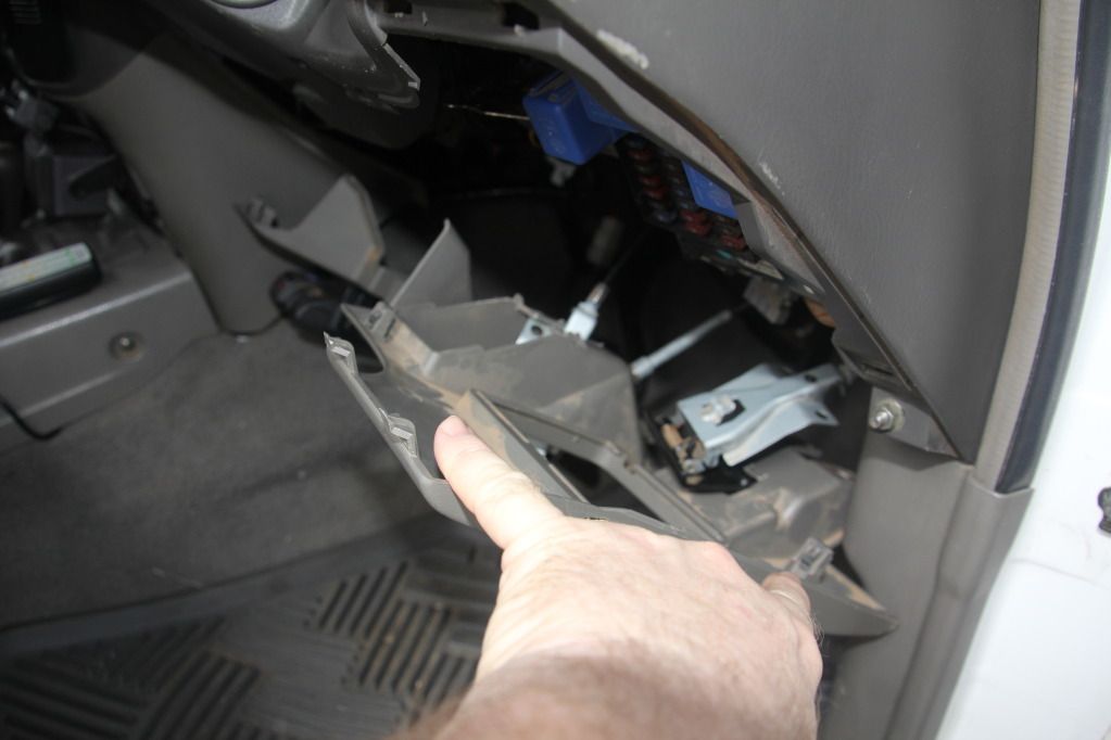
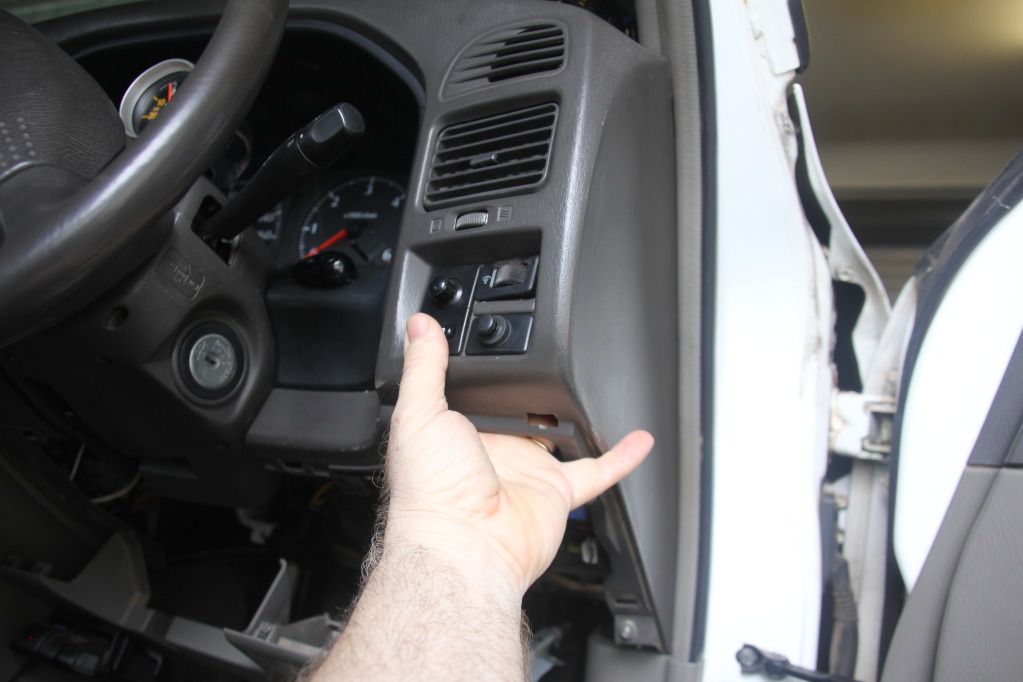
Now remove fuse panel cover, see photo.
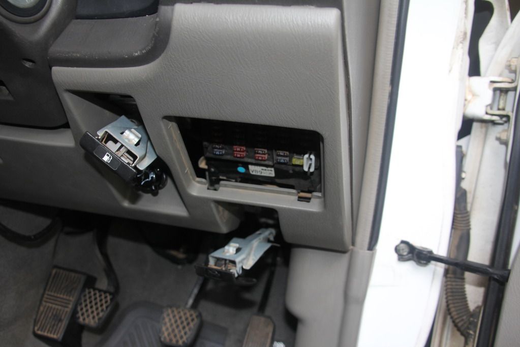
Now place you hand into fuse panel area and gentle grab and pull down and out towards you, this will release this panel so you now have easy access area to work with behind the dash.
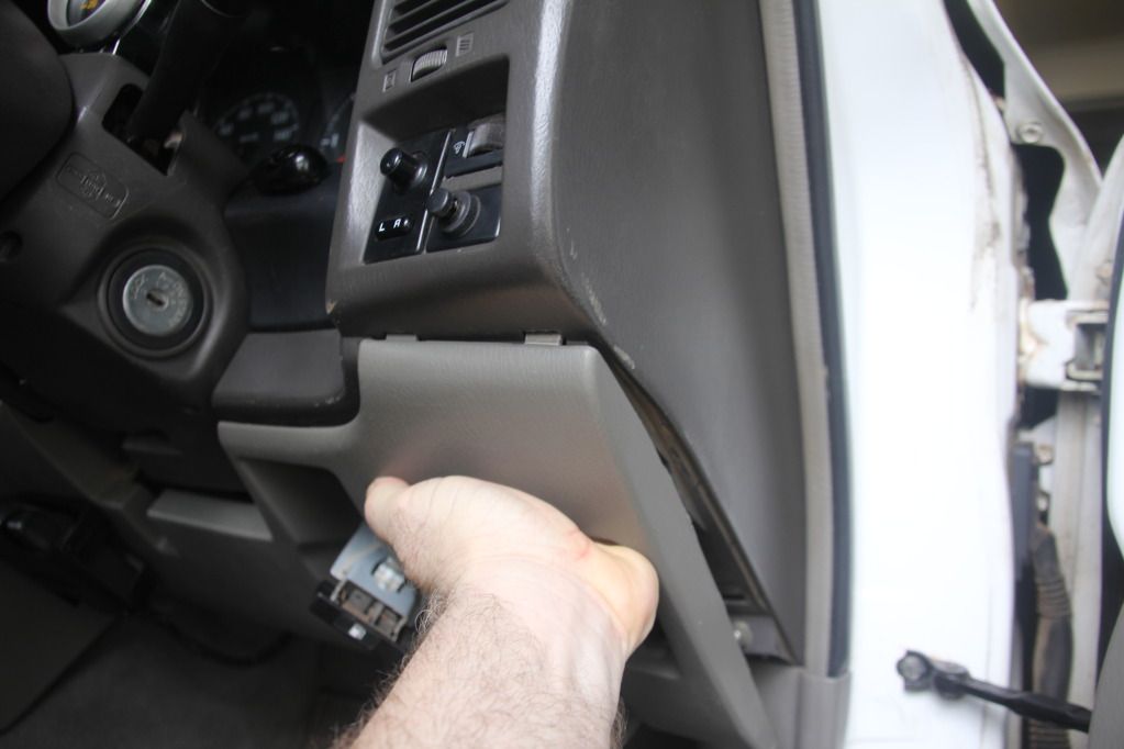
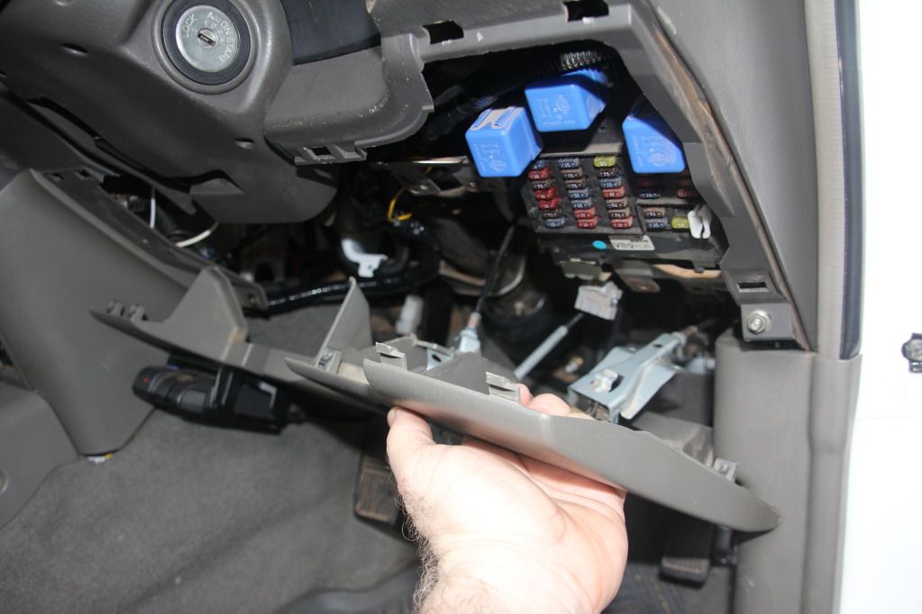
Now you should have access to both pillar and dash areas!
Finally, the center consul area, remove the ash-tray from the center consul.
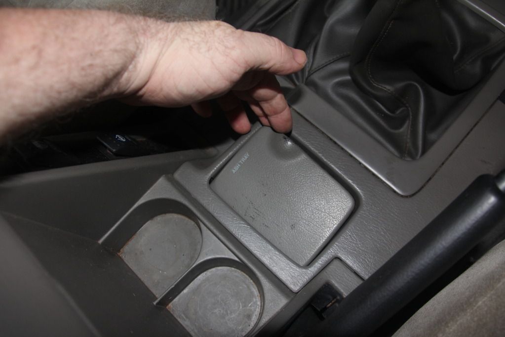
With the ash-tray removed, use a small Phillips head screw driver to remove the screw! see photo
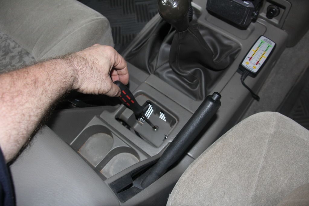
Now remove the two small screws at the front of the consul using a small Phillips head screw driver! see photo
Now remove both the transfer lever and gear-stick knobs. Gentle lift the panel up enough to access the ashtray light connector. disconnect by gently depressing the middle of the connector and pull the two apart. Now remove this panel.
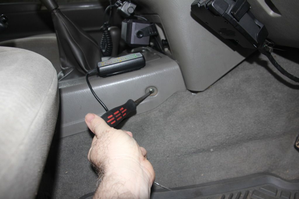
Finally, undo the two small screws at the bottom of the cigarette lighter panel. Gently pull down on the panel and now you have access to all your working areas.
more to follow over!
The halls been rented the bands been paid, time to see you dance!
-
The Following 2 Users Say Thank You to PMC For This Useful Post:
MC97GQ (29th December 2012), NissanGQ4.2 (1st January 2013)
-
29th December 2012, 05:53 PM
#3
Part 3
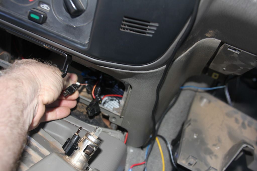
Disconnect both the light and cigarette lighter connectors see photo
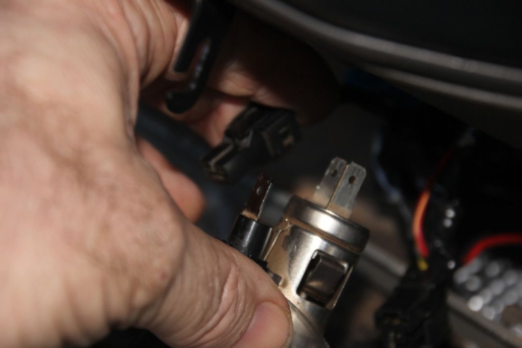
The following are where you are going to splice and solder your wiring from your gauges into. Firstly, wiring from Boost, Oil and Water temp lights will be spliced and solder into the Cigarette light wiring. Secondly, the light wiring for the EGT will be spliced and solder into the Cigarette housing wiring loom.
From the oil gauge and water temp in the pod. (you may decide to run your Boost and EGT gauges from the pillar pod) Run both red positive wires down though and under dash to light connector on the cigarette lighter. Now splice the wire. Do not solder until you have the Boost (white wire), Oil and Water temp (Red wires) run to the light connector on the cigarette lighter.
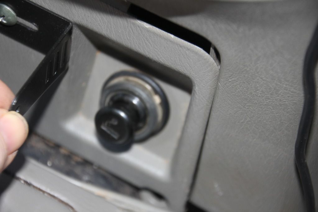
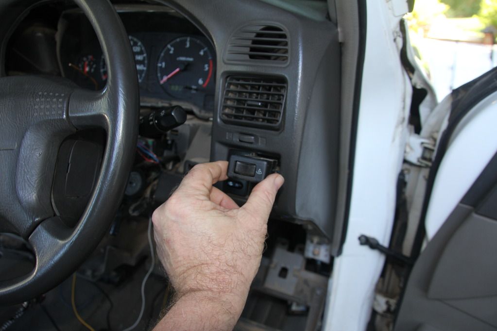
Now pop out the dimmer switch out, see photo;
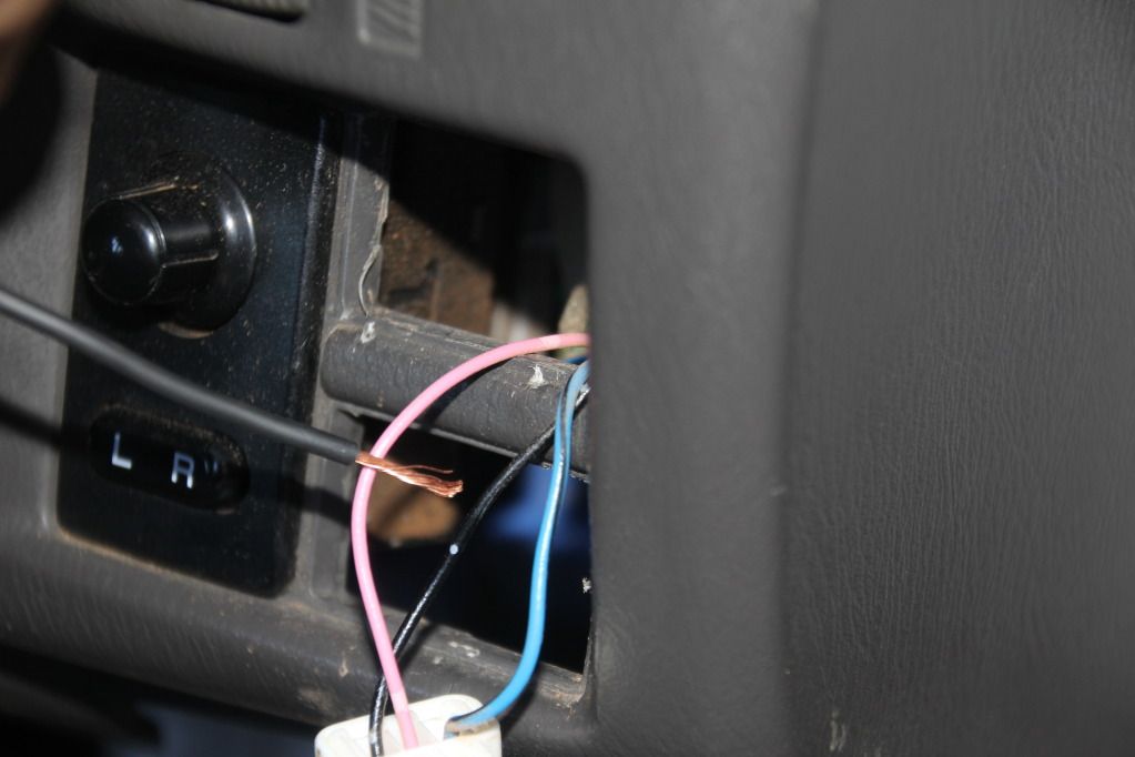
With the dimmer switch removed, Splice the 3 black wires from the Boost, Oil and Water temp gauges lights into the pink wire that goes into the dimmer switch (Not the blue wire ) See photo below. This now allows you to operate you new gauges lights only at night time when you turn on your head-lights. By wiring into the dimmer switch, you have the additional ability to dim you gauges, if you do not like bright lights.
With your EGT gauge light, Red wire goes to Cigarette lighter wiring, your black wire goes to earth on the body. When you turn your ignition on you have a lights at the EGT all the time.
When re-assembly of the panels, remember to align all locating clips with holes in other panel housings. see photos
Walla you goat stroker's, you've done it! Now go and have that beer and or any other stress relieve beverage that you usually drink!
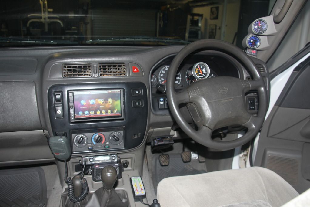
Finished look:
Regards,
RLI

The halls been rented the bands been paid, time to see you dance!
-
The Following 5 Users Say Thank You to PMC For This Useful Post:
L--RYDA (5th July 2014), Lonicus (29th December 2012), MC97GQ (29th December 2012), NissanGQ4.2 (1st January 2013), Stropp (29th December 2012)
-
29th December 2012, 06:52 PM
#4
Patrol Guru

Brilliant step by step mate!!
Exactly what people like me who are unsure about what, and how, to take apart the bits we need to to get things connected.
-
The Following User Says Thank You to Lonicus For This Useful Post:
-
29th December 2012, 08:10 PM
#5
Patrol God


Good stuff mate, just what I need, I am about to wire my low water alarm and was wondering where to get power from! Cheers for that.
-
The Following User Says Thank You to Stropp For This Useful Post:
-
1st January 2013, 06:04 PM
#6
excellent write up mate, thanks.
-
The Following User Says Thank You to Jodaniels For This Useful Post:
-
1st January 2013, 06:47 PM
#7
Patrol Freak

Hey mate - great guide and the photos make it easy for anyone to follow.
Jas
__________________________________________
Roads? Where we're going we don't need roads.......
2012 Silver GU 8. Bullbar, Warn XD9000 winch, snorkel, towbar, roof bars and rack, awning, 33" Mickey Thompson ATZ 4ribs, 2" lift - Dobinsons coils and Koni shocks, more to come......
2013 Travelling Wilbury's Cape York Trip - bring it on!
WARNING: Towballs used for recoveries can, and do kill people and damage property.
-
The Following User Says Thank You to lorrieandjas For This Useful Post:
-
2nd January 2013, 06:05 AM
#8
a member of the menagerie

Hey Paul,
Great write up mate well detailed and plenty of pics, only one complaint as it was done on a GU, you now need to get a GQ, MK/MQ and a G60, and do wiring write ups for these models.
Na serious mate good job.
Mark
Proud former owner of a 1997 White GQ TD42 Patrol Cab Chassis with an after market turbo, now with over half a million k's and still going strong, that's had a heart transplant and now not owned by me 
-
The Following User Says Thank You to MC97GQ For This Useful Post:
-
2nd January 2013, 11:12 AM
#9

Originally Posted by
MC97GQ

Hey Paul,
Great write up mate well detailed and plenty of pics, only one complaint as it was done on a GU, you now need to get a GQ, MK/MQ and a G60, and do wiring write ups for these models.
Na serious mate good job.
Mark
G'day Mark,
Supply me those vehicles, ill gladly do the write ups for everyone! lol
Regards,
RLI
The halls been rented the bands been paid, time to see you dance!
-
-
3rd July 2016, 10:41 AM
#10
Originally Posted by
PMC
Part 3
Disconnect both the light and cigarette lighter connectors see photo.........................................
I have tried following your wiring procedure step by step. after finishing I noticed that when I adjust the lights with the dimmer switch my gauges go mental. There is Boost, pyro, water temp and oil pressure, the are autotechina brand, all the yellow wires are the positive for the lighting and all black are negitive. I have had to revert back to all thee yellows going to headlight wire and black to negative, any advice would be appreciated as the lights are very bright at night
Last edited by NissanGQ4.2; 3rd July 2016 at 10:49 AM.
Reason: Removed all the images from the quote and a heap of text
-


 Reply With Quote