Welcome to the Nissan Patrol forum. To post a question and to see less adds on the forum then you will have to register
first. We are an easy going friendly forum so join in the conversations and feel free to ask any questions.
Become a forum sponsor for only $20 and see no adds with faster page loading times and many extras benefits.
Infomation Courtesey of Repco Autotech Encyclopedia 2006
NOTE; This information does not apply to 4.8 litre models.
Fault Codes
The 4 digit Fault Codes are displayed in two parts as flashes of the Check Engine Lamp.
The first part represents the first two digits of the fault code.
These are displayed as 0.6 second flashes.
The second part displays the second two digits of the fault code.
These are displayed as 0.3 second flashes.
There is a 0.9 second pause between the first and second parts of the code.
There is a 2.1 second gap between separate codes of different value.
Multiple codes will flash in order of numerical value, from lowest to highest.
Fault Code Erasure
Fault Code Erasure can be carried out with a Compatible Scan Tool or manually.
Manual Erasure:
1. Carry out Fault Code Extraction.
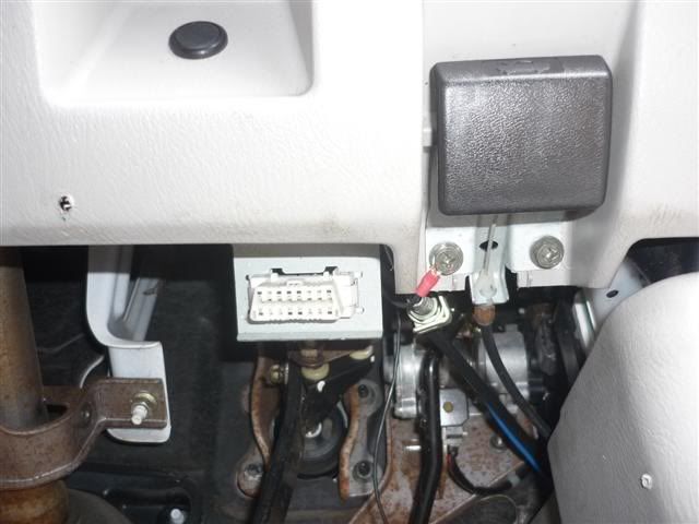
2. While the Fault Codes are being displayed, bridge Diagnostic Connector terminals 1 and 8.
3. Wait at least two seconds.
4. Disconnect the bridge between Diagnostic Connector terminals 1 and 8.
(This will erase the Fault Codes from ECM memory)
Should the above procedure fail to erase the Fault Codes;
Disconnect the battery negative cable or remove power to the ECM for 24 hours.
Ensure that other memory codes are known prior to performing this procedure.
Fault Code Extraction
Fault Code Extraction can be carried out with a Compatible Scan Tool or manually.
Manual Extraction:
1. Switch ignition ON.
2. Confirm the Check Engine Lamp illuminates.
(The system will be in Diagnostic Test Mode I.)
3. Bridge Diagnostic Connector terminals 1 and 8.
Confirm the Check Engine Lamp extinguishes.
4. Wait at least two seconds.
5. Disconnect the bridge between Diagnostic Connector terminals 1 and 8.
(The system will be in Diagnostic Test Mode II.)
6. Read Fault Codes as flashes of the Check Engine Lamp.
Do not switch ignition off during this procedure or the system returns to Diagnostic Test Mode I.
Fault Code Table
Code # Circuit and Status
0102 Mass Air Flow Sensor
Circuit, Sensor or ECM failure
0103 Engine Coolant Temperature Sensor
(excessively high or low voltage at ECM)
Circuit, Sensor or ECM failure
0104 Vehicle Speed Sensor
(signal not sent when vehicle is in motion)
Circuit, Sensor or ECM failure
0203 Accelerator Position Switch (incorrect signal sent to ECM)
Accelerator Position Switch fault or ECM failure
0208 Overheating Fault
Cooling Fan system failure, Engine coolant re-filling procedure not followed,
Cooling system faulty, Engine lubrication problem
0301 ECM 2, failure (calculation function is malfunctioning)
Internal IC failure
0402 Fuel Temperature Sensor
(incorrect signal for fuel temperature received)
Refer to Injection Pump Control Unit
Circuit, Sensor or ECM failure
0403 Accelerator Position Sensor
(out of range signal received from sensor or switch assembly)
Circuit malfunction, Accelerator Position Sensor failure,
Accelerator Pedal Dual Contact Position Switch failure, ECM failure
0406 INT/AIR volume (excessively high signal from Mass Air Flow Sensor)
Air Duct, Charge Air cooler, Variable Nozzle Turbo Charger Control System,
Variable Nozzle Turbo Charger, Mass Air Flow Sensor failure, Circuit malfunction
0407 Crankshaft Position Sensor
Circuit, Sensor or ECM failure
0502 Battery voltage (excessively high voltage sent to battery)
Incorrect jump starting, Battery, Alternator, ECM
0504 Automatic Transmission Communication Line
(ECM receives incorrect voltage from Transmission ECM)
Circuit malfunction, Automatic Transmission ECM
0505 No faults detected
Monitored circuits are operating normally
0701 Camshaft Position Sensor
(incorrect signal from the Injection Pump Control Unit)
Refer to Injection Pump Control Unit
Circuit malfunction, Injection Pump Control Unit
0702 Top Dead Centre Pulse Signal
(incorrect signal from the Injection Pump Control Unit)
Refer to Injection Pump Control Unit
Circuit malfunction, Injection Pump Control Unit
0703 Pump Communication Line
(incorrect signal from the Injection Pump Control Unit)
Refer to Injection Pump Control Unit
Circuit malfunction, Injection Pump Control Unit
0704 Spill Valve Circuit
Circuit malfunction, Injection Pump Control Unit
0705 Pump Control Module
Circuit malfunction, Injection Pump Control Unit failure
0706 Spill Valve
Circuit malfunction, Spill Valve, Injection Pump Control Unit
0707 Fuel Injection Timing Control System
Circuit malfunction, Injection Pump Control Unit failure, Poor fuel quality
0802 Barometric Pressure Sensor (built into the ECM)
Internal circuit malfunction, ECM failure
0804 ECM internal input signal processing function malfunctioning
ECM failure
The Following 16 Users Say Thank You to YNOT For This Useful Post:
AB (20th December 2010), Bob (2nd December 2014), Bruce McGregor (17th April 2015), Finly Owner (11th September 2010), Goat (1st September 2012), gxr (25th January 2011), jay see (23rd July 2014), Maarten (29th October 2011), mav345 (25th April 2012), mopper (26th April 2014), my third 256 (29th October 2011), NZDaz (28th November 2011), tadpole (7th September 2011), twisty (29th April 2012), vk3mnm (10th September 2012), Wetty (19th May 2012)


 Reply With Quote