OUR VIDEOS GALLERY MEMBER SPONSORSHIP VENDOR SPONSORSHIP

User Tag List

Page 4 of 5 FirstFirst ... 2345 LastLast
Results 31 to 40 of 44

Thread: GU Steering wheel audio controls install

  1. #31
    Beginner 4.8man's Avatar
    Join Date
    Feb 2011
    Location
    Brisbane Australia
    Posts
    12
    Thanks
    4
    Thanked 12 Times in 7 Posts
    Mentioned
    2 Post(s)
    Tagged
    0 Thread(s)
    Hi Cremulator. Looks good, I' thinking of installing the radio/volume/phone module as you have done. Where did you get the control module from? Cheers.

  2. The Following User Says Thank You to 4.8man For This Useful Post:

    Cremulator (4th June 2022)

  3. # ADS
    Circuit advertisement
    Join Date
    Always
    Location
    Advertising world
    Posts
    Many


  4. #32
    Patrol Guru Cremulator's Avatar
    Join Date
    Jun 2018
    Location
    Melbourne
    Posts
    562
    Thanks
    2,502
    Thanked 867 Times in 401 Posts
    Mentioned
    24 Post(s)
    Tagged
    0 Thread(s)
    Quote Originally Posted by 4.8man View Post
    Hi Cremulator. Looks good, I' thinking of installing the radio/volume/phone module as you have done. Where did you get the control module from? Cheers.
    Hey @4.8man I got them from Niss4x4 in Brooklyn (VIC). I paid $90 including the plug and cable that connects to the back.

  5. #33
    Beginner 4.8man's Avatar
    Join Date
    Feb 2011
    Location
    Brisbane Australia
    Posts
    12
    Thanks
    4
    Thanked 12 Times in 7 Posts
    Mentioned
    2 Post(s)
    Tagged
    0 Thread(s)
    Ok, thanks, I'll check them out.

  6. The Following User Says Thank You to 4.8man For This Useful Post:

    Cremulator (5th June 2022)

  7. #34
    Beginner 4.8man's Avatar
    Join Date
    Feb 2011
    Location
    Brisbane Australia
    Posts
    12
    Thanks
    4
    Thanked 12 Times in 7 Posts
    Mentioned
    2 Post(s)
    Tagged
    0 Thread(s)
    Hi all, I've advanced a little now, have bought the control switch from Niss 4X4, for $200 plus postage, they wouldn't come down on their price! Oh well will move on.
    It has 4 wires coming out of the switch, plus a tab spliced on, witch I presume is for the horn, or earth? Not sure what vehicle it came out of, and looks like it has been modified already.

    Attachment 85915ý

    At first, after looking into the install job, it seemed a bit complex, so I contacted some professionals, mobile and retail radio installers, but they weren't keen to do the job!
    So after thinking a bit more, and investigating my wagon (2002 4.8lt. Petrol model) it's looking straight forward, and may not be as complex as first thought, as long as the following work:
    So my wagon has a cruise control system and switch installed from factory built and also a steering wheel air bag.
    The air bag has its own yellow plug and 2 wires going through the clock spring. The cruise control has 2 wires and the horn, 1 wire going through a white plug, going through the clock spring, all on the air bag side of the clock spring.

    20220612_145644.jpg

    As you can see, there are 2 spare terminal slots, in the white plug.
    On the other side of the white plug, going into the clock spring, there are 5 wires going through the clock spring.

    20220709_151131.jpg

    On the other side of the clock spring (under the steering column) there is 7 wires coming out. Therefore that must include the 2 spare wires. Good news. Remember there is only 5 wires used to date; 2 for the cruise control, 2 for the air bag, and 1 for the horn.

    My head unit is a Pioneer AVH-Z5250BT and doesn't require an intetface module to make the steering wheel switch to work.

    20220610_104329.jpg

    It has a single radio jack in the back of the head unit for the steering wheel control.

    20220521_115757.jpg

    So I'm thinking: could I just join/soldier 2 pairs of the 4 wires together to make 2 double wire to plug into the 2 spare terminals in the white plugs, leading into the clock spring. Then pick them up on the outward side of the clock spring, find out where they run to/install new wires and plug them into the back of the head unit with a new jack plug?
    Sounds simple, but is there something I'm missing?

    Thanks in advance, cheers, Col.

  8. #35
    Patrol Guru Cremulator's Avatar
    Join Date
    Jun 2018
    Location
    Melbourne
    Posts
    562
    Thanks
    2,502
    Thanked 867 Times in 401 Posts
    Mentioned
    24 Post(s)
    Tagged
    0 Thread(s)
    Quote Originally Posted by 4.8man View Post
    Hi all, I've advanced a little now, have bought the control switch from Niss 4X4, for $200 plus postage, they wouldn't come down on their price! Oh well will move on.
    It has 4 wires coming out of the switch, plus a tab spliced on, witch I presume is for the horn, or earth? Not sure what vehicle it came out of, and looks like it has been modified already.

    Attachment 85915ý

    At first, after looking into the install job, it seemed a bit complex, so I contacted some professionals, mobile and retail radio installers, but they weren't keen to do the job!
    So after thinking a bit more, and investigating my wagon (2002 4.8lt. Petrol model) it's looking straight forward, and may not be as complex as first thought, as long as the following work:
    So my wagon has a cruise control system and switch installed from factory built and also a steering wheel air bag.
    The air bag has its own yellow plug and 2 wires going through the clock spring. The cruise control has 2 wires and the horn, 1 wire going through a white plug, going through the clock spring, all on the air bag side of the clock spring.

    20220612_145644.jpg

    As you can see, there are 2 spare terminal slots, in the white plug.
    On the other side of the white plug, going into the clock spring, there are 5 wires going through the clock spring.

    20220709_151131.jpg

    On the other side of the clock spring (under the steering column) there is 7 wires coming out. Therefore that must include the 2 spare wires. Good news. Remember there is only 5 wires used to date; 2 for the cruise control, 2 for the air bag, and 1 for the horn.

    My head unit is a Pioneer AVH-Z5250BT and doesn't require an intetface module to make the steering wheel switch to work.

    20220610_104329.jpg

    It has a single radio jack in the back of the head unit for the steering wheel control.

    20220521_115757.jpg

    So I'm thinking: could I just join/soldier 2 pairs of the 4 wires together to make 2 double wire to plug into the 2 spare terminals in the white plugs, leading into the clock spring. Then pick them up on the outward side of the clock spring, find out where they run to/install new wires and plug them into the back of the head unit with a new jack plug?
    Sounds simple, but is there something I'm missing?

    Thanks in advance, cheers, Col.
    I can't see the first photo you posted, doesn't load for some reason, but you are on the right track with your investigations tracing the wires through the clock spring.
    Have a look at post #12 in this thread and you can see exactly the two wire loom you are describing that I made that connects to the audio jack.

  9. #36
    Beginner 4.8man's Avatar
    Join Date
    Feb 2011
    Location
    Brisbane Australia
    Posts
    12
    Thanks
    4
    Thanked 12 Times in 7 Posts
    Mentioned
    2 Post(s)
    Tagged
    0 Thread(s)
    Quote Originally Posted by Cremulator View Post
    I can't see the first photo you posted, doesn't load for some reason, but you are on the right track with your investigations tracing the wires through the clock spring.
    Have a look at post #12 in this thread and you can see exactly the two wire loom you are describing that I made that connects to the audio jack.
    Thanks for the quick reply. Just a quick side note do you get notifications when a reply is posted on your post?
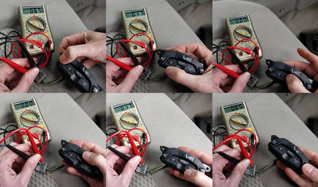
    Another point, did you have to check the resistant values on the wiring from the switch? if so, how did you check them with a multi meter?
    I'll try posting the first pic. again as above:

    20220802_091601.jpg

    20220802_091631.jpg

    Above is my switch I bought
    It came an ugly light beige colour. I painted it the dark brown colour to try and match my wagons colour scheme!

  10. #37
    Patrol Guru Cremulator's Avatar
    Join Date
    Jun 2018
    Location
    Melbourne
    Posts
    562
    Thanks
    2,502
    Thanked 867 Times in 401 Posts
    Mentioned
    24 Post(s)
    Tagged
    0 Thread(s)
    Sometimes I get notifications when there is a reply posted, not always.

    I checked the switch values with a multimeter, they are all different so no need to use any resistors.


    That module you have, along with the loom and plug, looks identical to what I purchased.
    Follow the directions I have posted above and you should have no trouble getting it all working.

    Post up any questions you have and I'll be happy to help out.

  11. #38
    Beginner 4.8man's Avatar
    Join Date
    Feb 2011
    Location
    Brisbane Australia
    Posts
    12
    Thanks
    4
    Thanked 12 Times in 7 Posts
    Mentioned
    2 Post(s)
    Tagged
    0 Thread(s)
    Great. Looks like your like me, taken lots of photos!
    So what terminals did you touch with the multi meter probs? Is one of the wires/terminals, an earth?
    Cheers.

  12. The Following User Says Thank You to 4.8man For This Useful Post:

    Cremulator (14th September 2022)

  13. #39
    Patrol Guru Cremulator's Avatar
    Join Date
    Jun 2018
    Location
    Melbourne
    Posts
    562
    Thanks
    2,502
    Thanked 867 Times in 401 Posts
    Mentioned
    24 Post(s)
    Tagged
    0 Thread(s)
    I'm pretty sure the yellow wire is the earth, so test the other three terminals as positive while pressing the buttons.
    The good thing is, using trial and error with a multimeter to measure resistance won't damage anything as there is no voltage or polarity that you can mess up.
    Have a look at post #8 in this thread and you can see how I temporarily wired the plug to the buttons to test functionally on the head unit. This is more useful than testing resistance of each button with a multimeter as you can understand the wiring, then just work out extending it through the clock spring (use the pins in that large redundant plug you got with the audio buttons).

  14. #40
    Beginner 4.8man's Avatar
    Join Date
    Feb 2011
    Location
    Brisbane Australia
    Posts
    12
    Thanks
    4
    Thanked 12 Times in 7 Posts
    Mentioned
    2 Post(s)
    Tagged
    0 Thread(s)
    Ok, thanks. Why do you splice the audio yellow wire to the cruise control green wire?
    Also, on the radio side of the loom you made, is that an earth open tag that needs to be connected to ground somewhere?

Page 4 of 5 FirstFirst ... 2345 LastLast

Posting Permissions

  • You may not post new threads
  • You may not post replies
  • You may not post attachments
  • You may not edit your posts
  •